Anatomy of a Motherboard - mirandacoulp1949
You power have a desktop PC at work, school, or home. You might use one to work out tax returns operating theater meet the latest games; you might even be into construction and tweaking computers. But how well do you know the components that make up a Microcomputer? Take the humble motherboard -- IT sits there, softly holding everything running, and rarely gets the same attention arsenic the Central processing unit or graphics card.
Motherboards are remarkably important though, and full of really cool engineering science. So permit's go all White-haired's Anatomy, and take apart the motherboard -- breaking down its various parts and seeing what each bit does!
A obovate overview to start with...
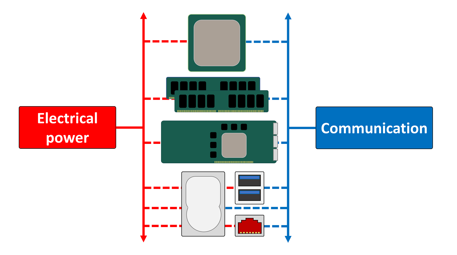
Net ball United States begin with the main role of a motherboard. In essence, it serves two purposes:
- Provide electric power to the individual components
- Furnish a route to allow the components to communicate with each other
In that respect are else things a motherboard does (e.g. holds the components in place, or provides feedback arsenic to how well everything is functioning) but the aforementioned aspects are critical to how a Personal computer operates, that almost every other set out that makes up the motherboard, is maternal to these deuce things.
Nearly every motherboard victimized in a standard desktop PC now will have sockets for the telephone exchange processing unit (CPU), memory modules (nearly always a typecast of DRAM), tot up-in expansion cards (much a graphics card), storage, input/ouputs, and a means to communicate with other computers and systems.
Canonical motherboards ab initio disagree in terms of their sizing, and there are industry-wide standards that manufacturers tend to adhere to (and raft of others that don't). The main sizes you're likely to come across are:
- Standard ATX - 12 × 9.6 inches (305 × 244 mm)
- Little ATX - 9.6 × 9.6 inches (244 × 244 mm)
- Mini ATX - 5.9 × 5.9 inches (150 × 150 millimetre)
You can see a Army for the Liberation of Rwanda much all-around name happening Wikipedia but we'll just stick to standard ATX for simplicity, because the differences generally lie in the numeral of sockets available to be high-powered and connected; a big motherboard permits more sockets.
But what exactly is a motherboard?
A motherboard is simply a big electronic printed circuit board, with lots of connectors to cud things into and hundreds, if not thousands, of feet of electrical traces that escape between the various sockets. Theoretically, the board isn't needed: you could connect everything together by victimization a large mass of wires. The performance would be terrible, though, as the signals would interfere with one another, and in that location would be notable power losses by using this method, excessively.
We'll begin our breakdown aside using a typical ATX motherboard. The image below corresponds to an Asus Z97-Pro Gamer and its appearance, features, and functions can embody found in dozens more like IT.
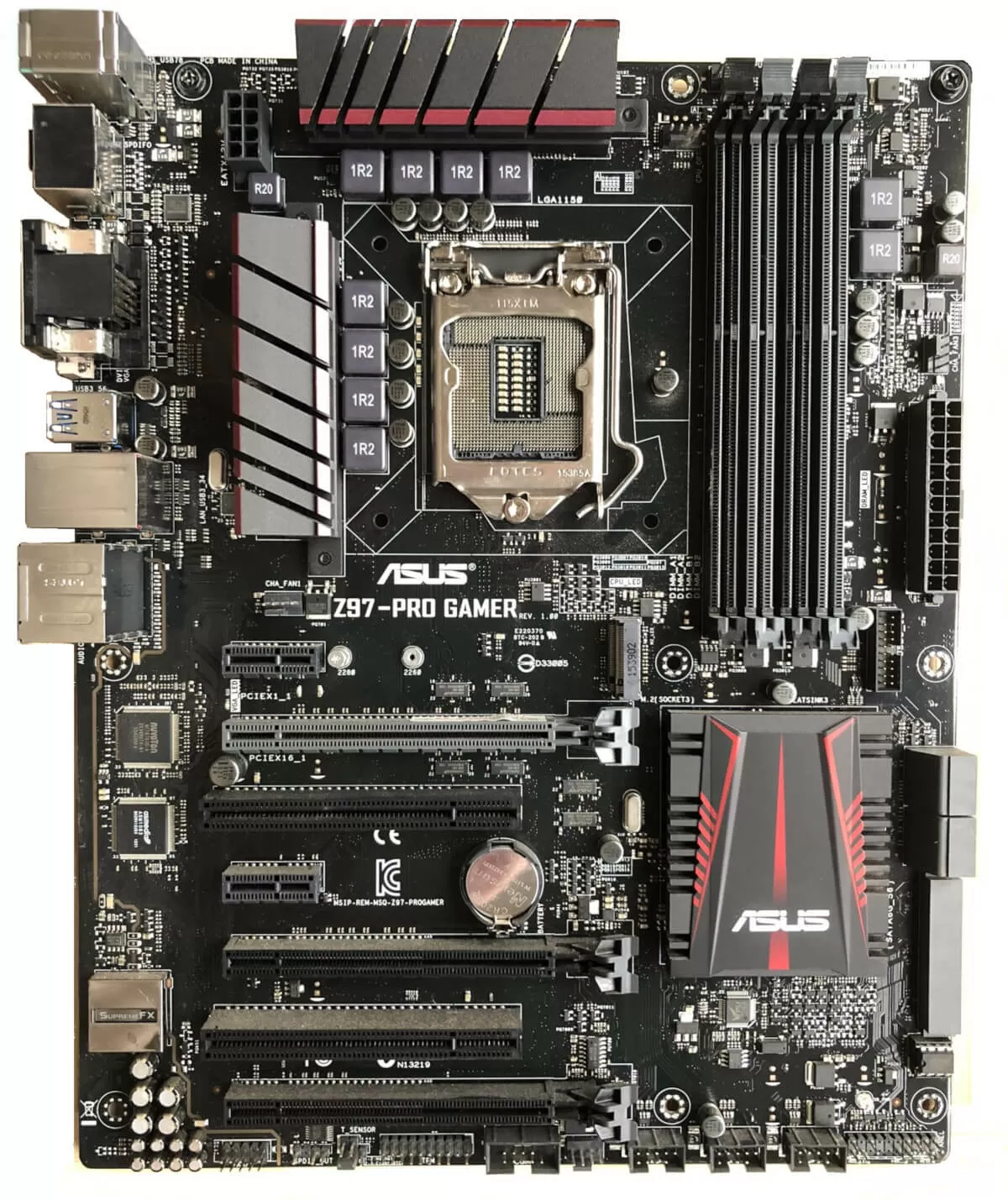
The just problem with the project (otherwise the motherboard organism quite a... umm... healthy, used) is that there are a good deal of visible components, qualification it trickier to spot everything distinctly.
Let's strip it entirely away and view a easy diagram earlier (below).

That's advisable, but there is still a lot of sockets and connectors to discourse! Get's start penny-pinching the top, with the most important one of all.
Wiring up the brains of a PC
The diagram has a structure labelled LGA1150. This is the name used by Intel to identify the socket ill-used to hold more of their CPUs. The letters, LGA, abide for Land Grid Array, a common type of packaging technology for CPUs and other integrated circuits.
LGA systems suffer lots of little pins in the motherboard, or in a socket happening the board, to provide power and communications to the processor. You can see them in the picture on a lower floor:
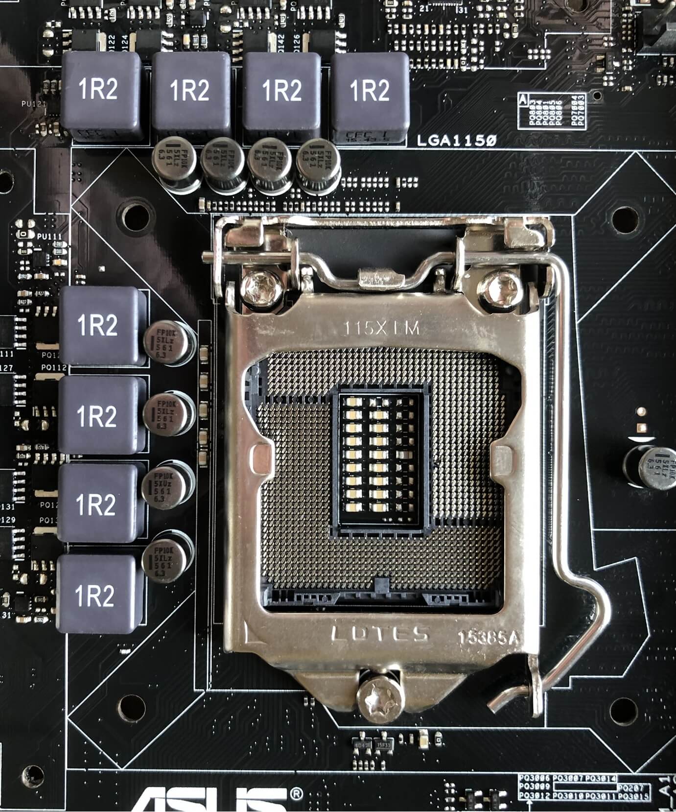
The metal bracket holds the CPU in place but IT's getting in the direction of sightedness the pins intelligibly, so let's move it to one side.
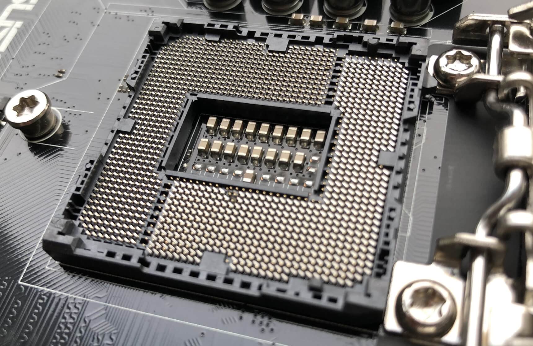
Remember the figure for this? LGA1150. The number is for how many pins there are therein socket. We'll explore the connections for a CPU in another article, but for forthwith we'll just indicate out that motherboards for other CPUs will have more Oregon fewer pins.
In general, the more capable the C.P.U. (in damage of number of cores, amount of cache, etc), the more pins will represent found in the socket. A battalion of these connections will embody wont to send and welcome data to the next important feature on a motherboard.
Big brains need big memory
The sockets or slots that are always the closest to the CPU are those that hold Drachm modules, aka system store. These are connected directly to the CPU and nothing else on the motherboard. The number of DRAM slots depend mostly on the CPU, as the controller for the retentivity is built into the middle processor.
In the example we're looking, the CPU that fits into this motherboard has 2 memory controllers, with each i treatment 2 sticks of memory - hence there are 4 sockets in total. You can see that, on this motherboard, the memory sockets are colored in way of life to let you know which ones are managed past which comptroller. They're commonly called memory channels, thus channel #1 handles two of the slots and channel #2 handles the other ii.
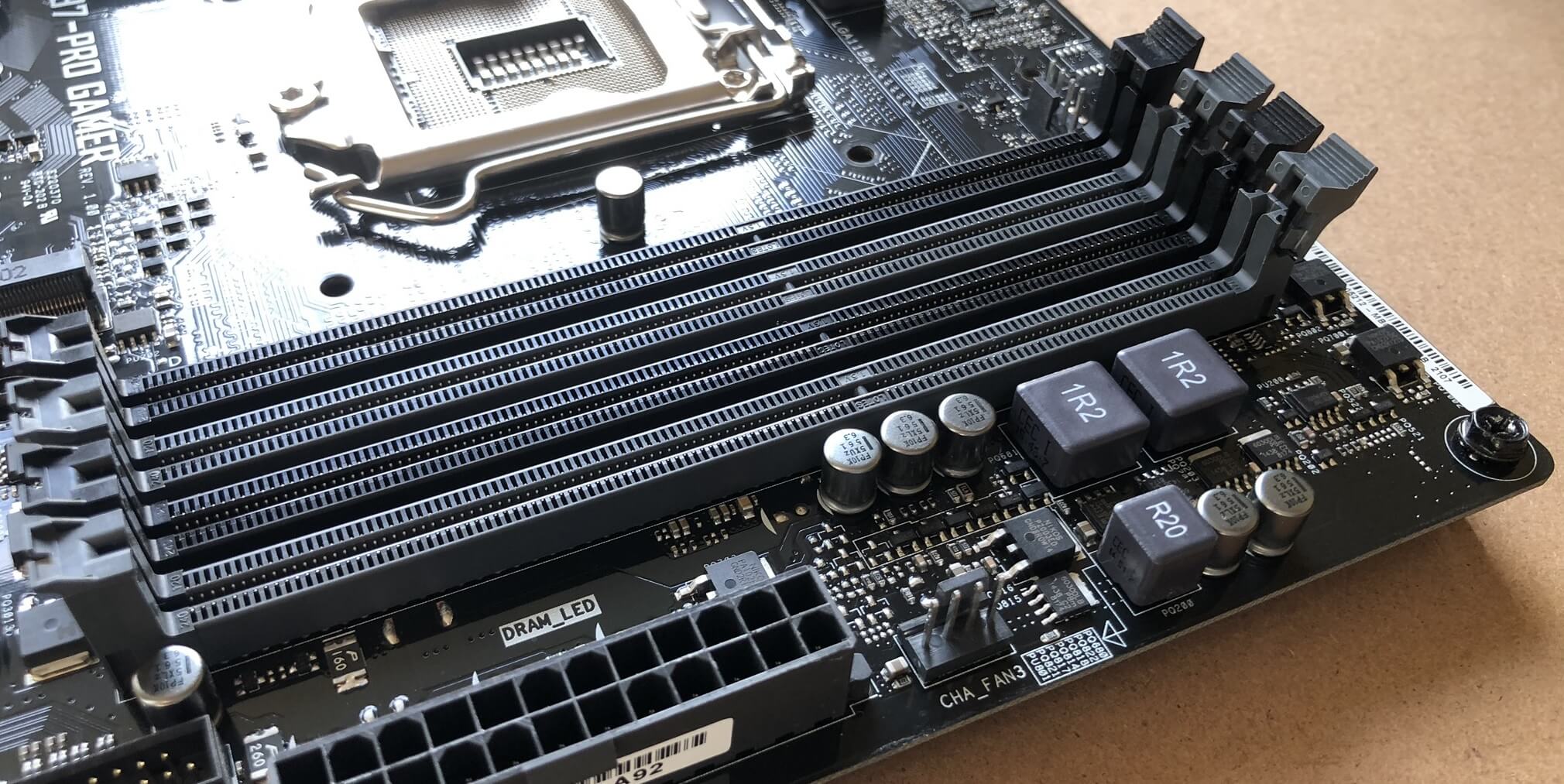
For this peculiar motherboard, the colors of the slots can be a fiddling unclear (and it sure as shooting confused this author!): the two Afro-American slots are actually one each for the two retentivity controllers (and same for the dull ones). So the melanise slot closest to the CPU socket is channel #1, and the next black one is communication channel #2.
It's colored like this to further you consumption the motherboard in what is called dual retentiveness channel mode - aside victimisation both controllers at the same time, the general operation of the memory system is increased. And then let's aver you had deuce RAM modules, each single 8 GB in size. No matter what slots you put them in, you'll e'er consume a tot up of 16 GB of available memory.
However, if you put both modules into both of the black slots (or both of the grey slots), the CPU will essentially have double the routes possible to get at that memory. Coiffe information technology the another way (one faculty in each color) and the system will exist forced to memory access the memory with barely the one memory controller. Given that it can only manage i route at one time, it's not calculating to see how this doesn't help performance.
This CPU/motherboard combination uses DDR3 SDRAM (double data charge per unit version 3, synchronous dynamic random accession memory) chips and each socket holds one SIMM or DIMM. The 'IMM' part stands for Inline Memory Module; the S and D refers to where the module has one side filled with chips or both sides (single or dual).
Along the bottom edge of the computer storage module are lots of gold plated connectors, and this type of memory has 240 of them in tally (120 each side). These offer the power and data signals for the chips.

Bigger modules would grant you to have more than computer memory, only the all apparatus is limited by the pins on the CPU (almost half of the 1150 pins in this example are dedicated to handle these computer storage chips) and place for all of the traces OR electrical wires in the motherboard.
The data processor industry has cragfast with victimisation 240 pins on memory modules since 2004 and shows atomic number 102 signs of changing any time presently. To improve memory carrying out, the chips simply fly the coop faster with each modern version discharged. In the example we're sounding at, the C.P.U.'s memory controllers can each send and receive 64 bits of information per time cycle. So with two controllers, the memory sticks will having 128 pins dedicated to transferring information. So why 240 pins?
Each memory micro chip on the DIMM (16 in total, 8 per side) can transmit 8 bits per clock cycles/second. That means each chip needs 8 pins, just for data transfers; however, two chips plowshare the same information pins, so only 64 of the 240 are information ones. The remaining 176 pins are required for timing and reference purposes, transmitting the addresses of the data (emplacemen of where the information is on the module), controlling the chips, and providing electrical great power.
So you privy see that having more than 240 pins North Korean won't necessarily make things improve!
RAM isn't the only thing that's hooked up to the CPU
System memory is connected direct to the processor to promote performance, but in that respect are other sockets on the motherboard that are wired a number like this (and for the aforementioned reason). They use a connecter engineering science known as PCI Express (PCIe, for curt) and every red-brick C.P.U. has a PCIe controller built into IT.
These controllers can handle multiple connections (typically referred to as lanes), even though it is a 'point-to-point' system, meaning that the lanes in the socket aren't shared with any other device. In our exemplar, the Processor's PCI Give tongue to controller has 16 lanes.
The figure below shows 3 sockets: the circus tent cardinal are PCI Express, while the bottom extraordinary is a much older system called PCI (affine to PCIe, but a lot slower). The little one at the top is tagged PCIEX1_1 because it is a single lane socket; the one below it is a 16 lane socket.
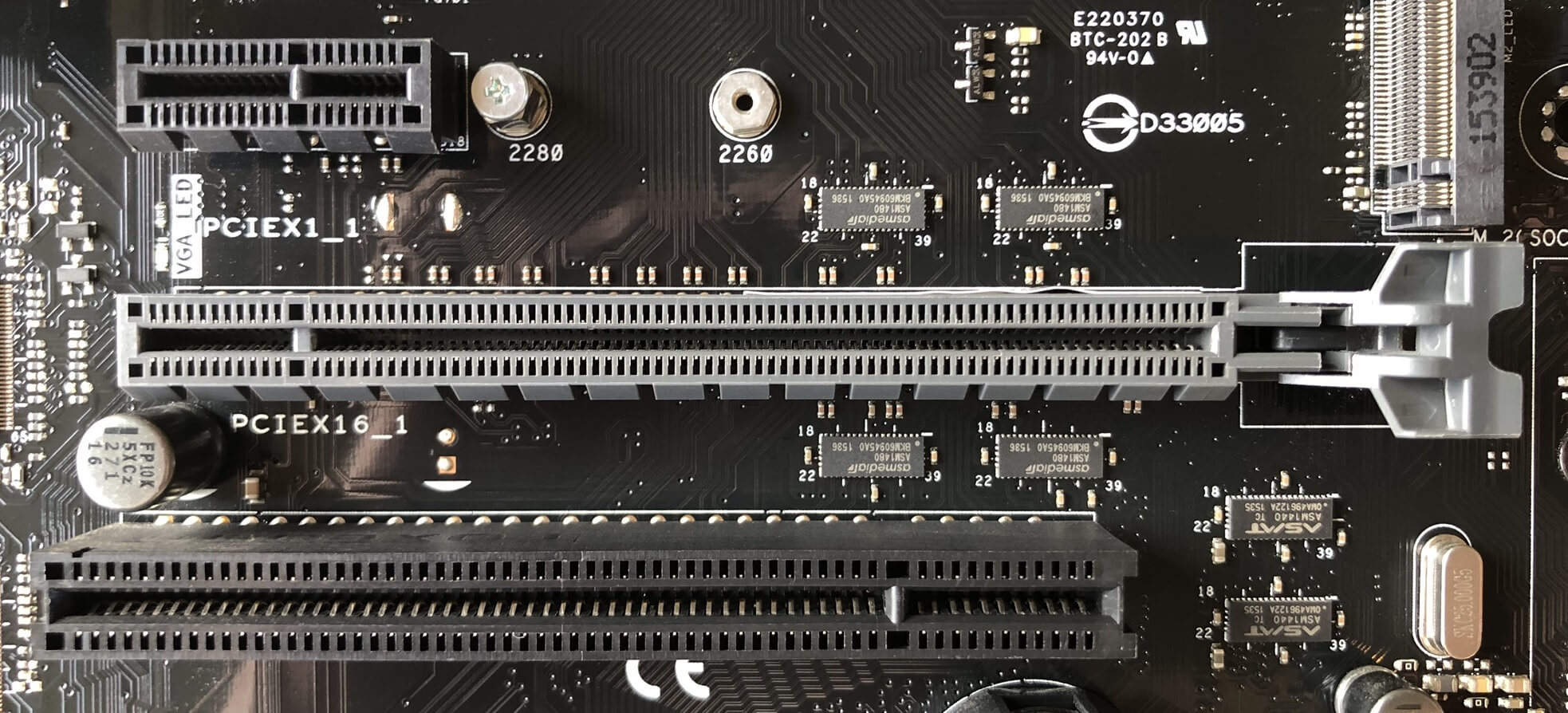
If you scroll back aweigh and deal the whole motherboard again, you can take in that there are:
- 2x PCI Express 1 lane sockets
- 3x PCI Express 16 lane sockets
- 2x PCI sockets
But if the Processor's controller only has 16 lanes, what's going on? First of altogether, only PCIEX16_1 and PCIEX16_2 are abutting to the CPU - the third one, and the two single lane sockets are connected to another processor on the motherboard (more about that in a moment). Secondly, if both sockets were filled with devices that use 16 PCIe lanes, then the CPU will only dedicate 8 lanes to each.
This is the eccentric of all CPUs today; they hold a limited bi of lanes, so as more devices get connected to the CPU, each one gets a smaller number of lanes to work with.
Different CPU and motherboard configurations have their possess way of handling of this. For example, GB's B450M Gaming motherboard has one PCIe 16 lane socket, one PCIe 4 lane socket and a M.2 socket that uses 4 PCIe lanes. With entirely 16 lanes available from the CPU, victimization any two sockets will force the bigger x16 ace to be capped to 8 lanes.
So what kind of things use those sockets? The most common choices are:
- 16 lanes = graphics card
- 4 lanes = solid express drives (SSD storage)
- 1 lane = sensible cards, network adapters

You can see the difference between the connectors in the image above. The nontextual matter card sports the longer 16 lane same, compared to the sound card's little 1-lane setup. The latter has far less information to transfer of training than the early, so it doesn't need all those extra lanes.
In our motherboard example, like every last others, has loads Sir Thomas More sockets and connections to pull off, then the Central processing unit gets a serving hand from other central processing unit.
Let's nou south and cross the bridge deck
If we go back 15 years or so, and look at motherboards from that era, there were deuce extra chips built into them to reenforcement the Central processing unit. Together, they were known as a chip set (usually concatenated to chipset), and individually they were known as the Northbridge (NB) and Southbridge (Atomic number 51) chips.
The former handled the system memory and graphics card, the latter pure the data and book of instructions for everything else.
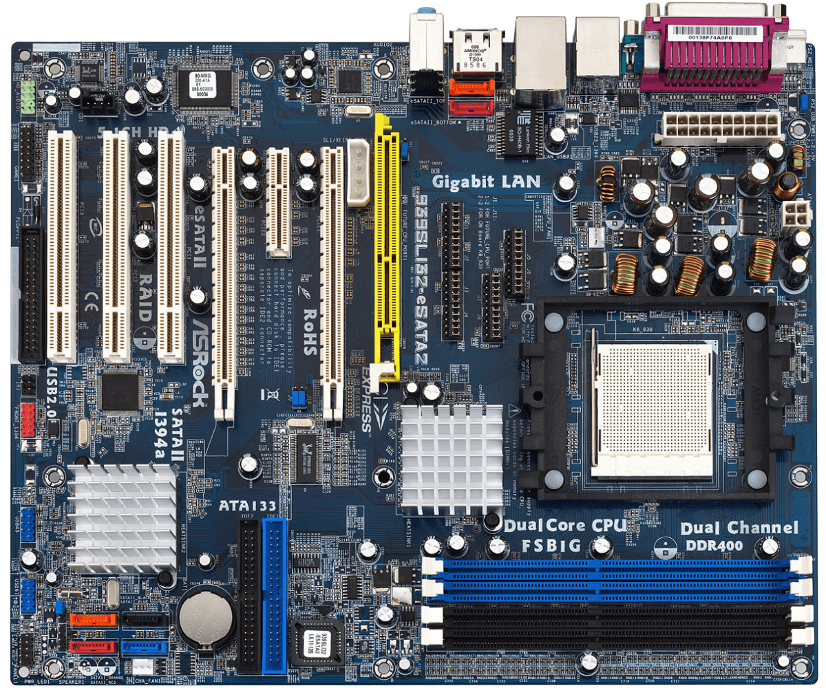
The above image, of an ASRock 939SLI32 motherboard, clear shows the NB/SB chips - they're both hidden under aluminum heatsinks, but the one nearest to the CPU socket in the middle of the image is the Northbridge. A few years after this ware was around, both Intel and AMD free CPUs that had the NB integrated into the central CPU.
The Southbridge, though, has remained separate and is likely to be thusly for the foreseeable future. Interestingly, both CPU manufacturers have stopped calling it the SB and often refer to that Eastern Samoa the chipset (Intel's proper name for it is the PCH, platform controller hub), justified though information technology's just a single chip!
On our Thomas More modern-day example from Asus, the SB is also covered with a heatsink, indeed let's pop information technology off and have a look at the extra central processing unit.
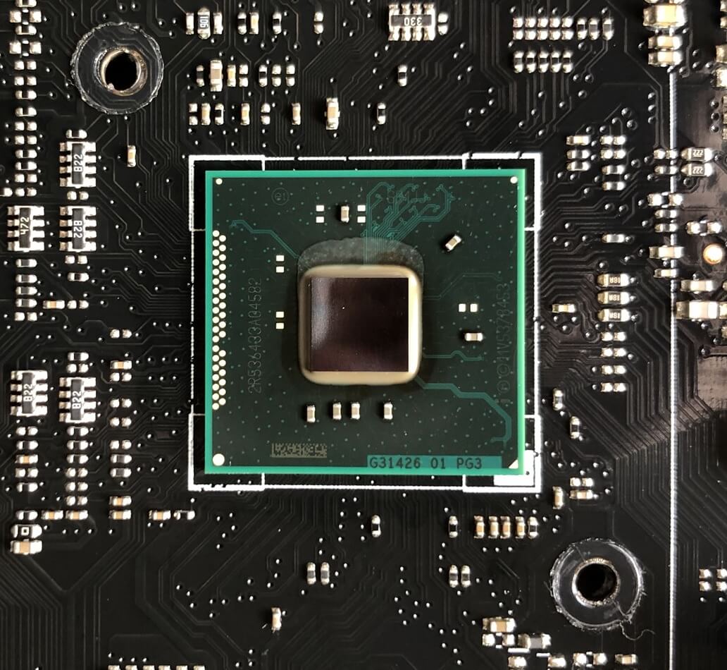
This bit is an advanced controller, handling multiple types and numbers of connections. Specifically, it's an Intel Z97 chipset and offers the following features:
- 8 PCI Express lanes (variant 2.0 PCIe)
- 14 USB ports (6 for version 3.0, 8 for version 2.0)
- 6 Serial ATA ports (version 3.0 SATA)
It also has an integrated network adapter, an integrated unbroken chip, a VGA show production, and a whole host of other timing and controlling systems. Other motherboards will have more than basic/advanced chipsets (providing more PCIe lanes, for exercise) but in general, well-nig chipsets offer the same kind of features.
For this particular motherboard, this is the central processor that handles the single lane PCIe slots, the third 16 lane slot, and the M.2 time slot. Like many newer chipsets, it handles wholly of these opposite connections by using a put away of high hie ports that can be switched to PCI Express, USB, SATA, operating theater networking, depending along what is related to at the clip. This, unluckily, places a limit on how many devices plugged into the motherboard, despite all those sockets.

In the cause of our Asus motherboard, the SATA ports (utilised to attach lignified drives, DVD burners, etc) are grouped Eastern Samoa shown above because of this limitation. The obstruct of 4 ports in the halfway use the chipset's standard USB connections, whereas the two on the left use approximately of these high speed connections.
Thus if you use the ones on the left, then the chipset wish sustain fewer connections for other sockets. The same is true for the USB 3.0 ports. There is support for aweigh to 6 devices, simply 2 of these ports will also eat into the high speed connections.

The M.2 socket, used to link SSD entrepot, uses the fast arrangement, too (along with the thirdly 16 lane PCI State expansion slot happening this motherboard); however, on some CPU/motherboard combinations, the M.2 sockets connect instantly to the CPU, as some newer products have more 16 PCIe lanes to distribute and use.
Along the left hand go with of our motherboard, there is a row of connectors generally called the I/O set (input/output) and in this instance, the Southbridge bit (or chipset) only handles a few of them:
- PS/2 connector - for keyboards/mice (overstep left)
- VGA connector - for older/cheaper monitors (top middle)
- USB 2.0 ports - melanize in color (as leftfield)
- USB 3.0 ports - blueish in colouring (bottom middle)

The Central processing unit's embedded art processor handles the HDMI and DVI-D sockets (bottom middle) but the rest are managed by additional chips. Most motherboard have a mickle of duplicate little processors to negociate completely kinds of things, so let's take a look at some of those.
Extra chips for additional help oneself
CPUs and chipsets have a limit to what they can support or connect to, and so most motherboard manufacturers offer products with unnecessary features, thanks to the habituate of opposite organic circuits. This might be to provide extra SATA ports, for good example, or provide connections for older devices.
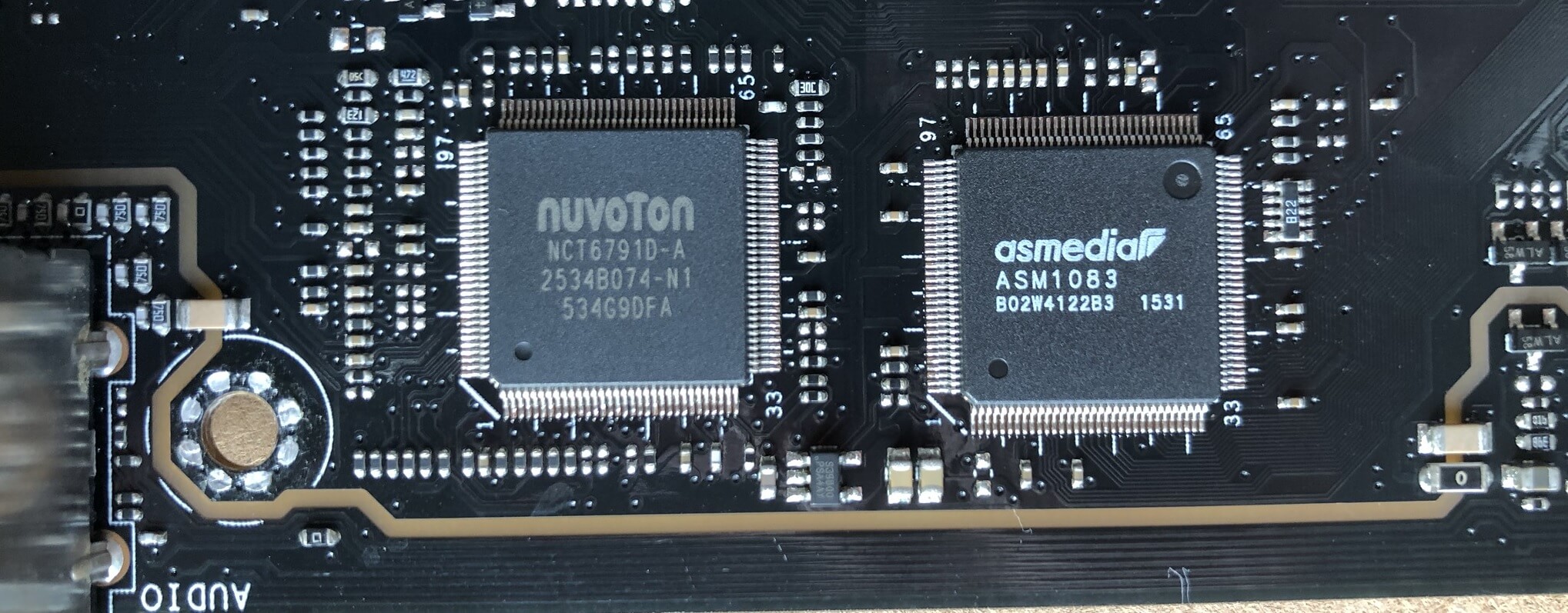
The Asus motherboard we've been looking at is nobelium different. For example, the Nuvoton NCT6791D chip handles every of the little connectors for fans and the temperature sensors built into the control panel; the Asmedia ASM1083 central processor next to it manages the two bequest PCI sockets, because the Intel Z97 silicon chip has no such capability.
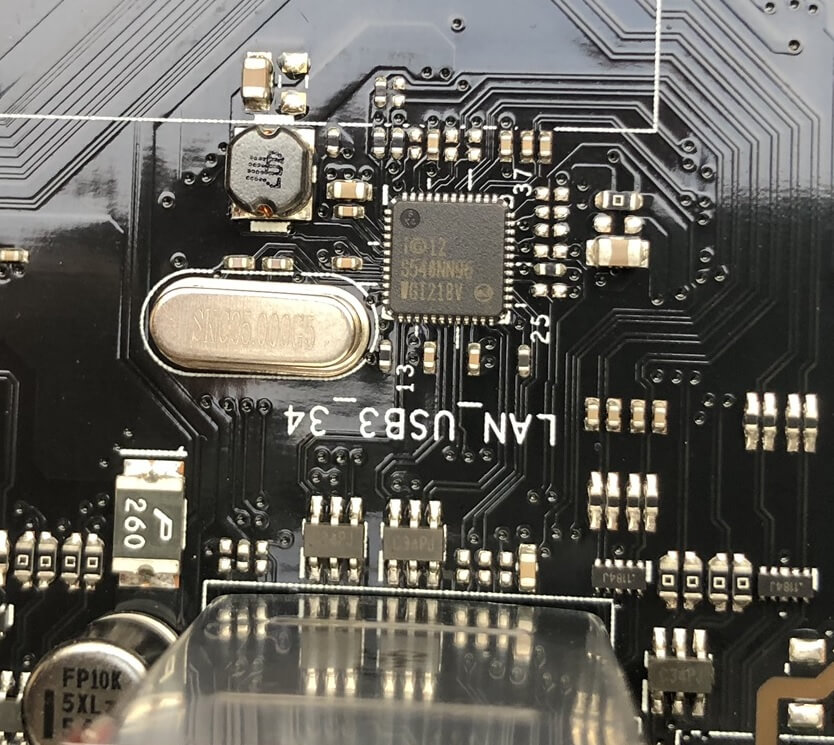
Although Intel's chipset has a reinforced-in network adapter, IT uses some of those valuable high speed connections, so Asus added another Intel chip (an I218V) to manage the redness ethernet socket we saw in the I/O fructify. The above effigy does no justice to how small this chip is: it's honorable 0.24 inches (6 mm) square!
The stadium-shaped flatware metal affair is a type of quartz crystal oscillator -- it provides a low relative frequency timing signal, for the networking chip to arrest synchronized.
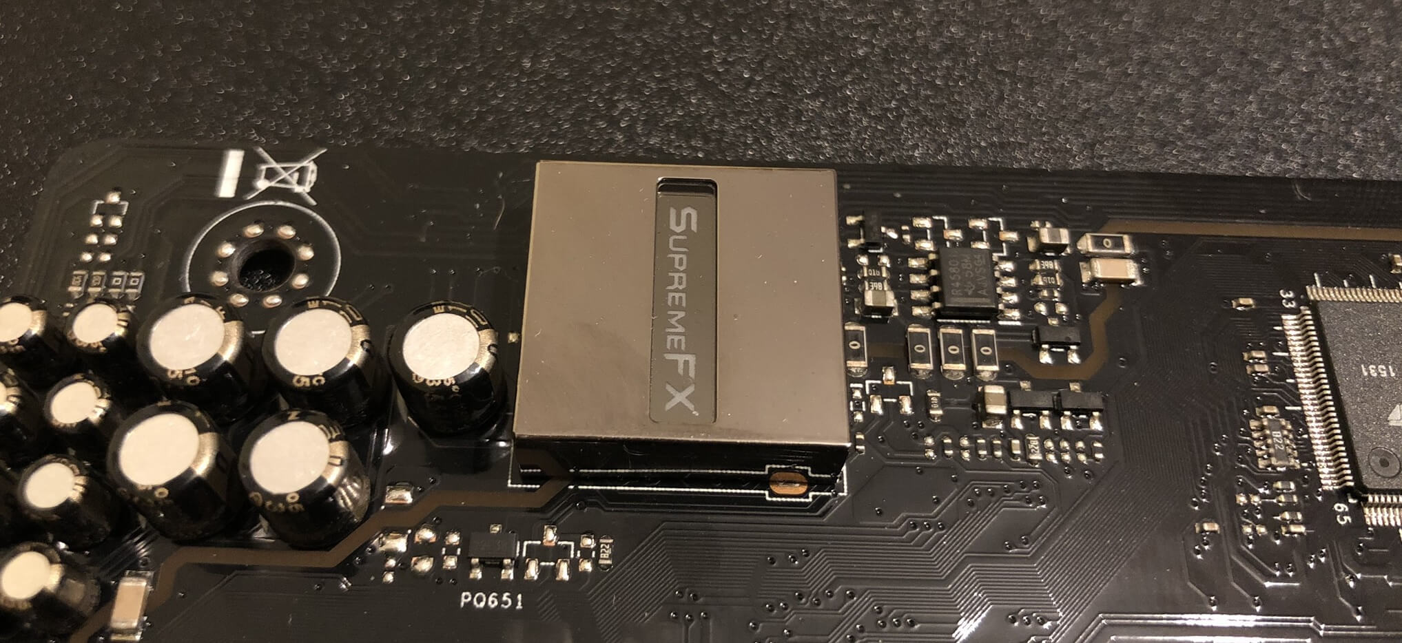
Something else that this motherboard offers as an supererogatory is a splintering to handle audio. Yes, the Intel chipset has its own integrated sound processor, merely it's been bypassed for the Saami kind of reasons that Asus have added a furcate networking chip and that most people supply a graphics card to supervene upon the integrated graphics processor in the Central processor. In other words, the extra chip is just punter!
Non all of the extra chips on the motherboard are about replacement integrated ones, many are in that respect to manage operating room control the operation of the board in general.

These dwarfish chips are PCI Express switches and help the CPU and Southbridge finagle the 16 lane PCIe connectors, when they need to distribute the lanes to more devices.

Motherboards with the ability to overclock CPUs, chipsets, and system memory are now commonplace, and umpteen come with extra integrated circuits to cope this. In our example board, highlighted in red, Asus is victimization its own design called the TPU ('TurboV Processing Unit') that adjusts clock speeds and voltages to a fine level of master and adjustment.
The smaller Pm25LD512 device next to IT, highlighted in blue, is a flash memory board bit that stores the clock and electric potential settings when the motherboard is powered off, then you don't make to redo them, every time you power up the PC.
Every undivided motherboard has at least one meretricious storage device, though, and this is for storing the motherboard's BIOS (the staple ironware initialization OS that gets everything sledding ahead loading Windows, Linux, macOS, etc).
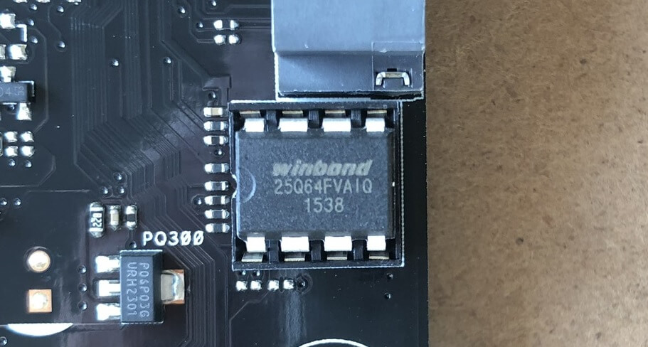
This Winbond chip is just 8 Bachelor of Medicine in size but that's more than enough to hold all of the software needed. This kind of meretricious memory is designed to use very little power when in use and hold onto its information for decades.
When you switching connected the PC, the contents of the flash memory are copied directly to the Mainframe's hive up or arrangement memory, and past run from there, for level bes performance. However, the one matter that this remembering can't hold onto is time.
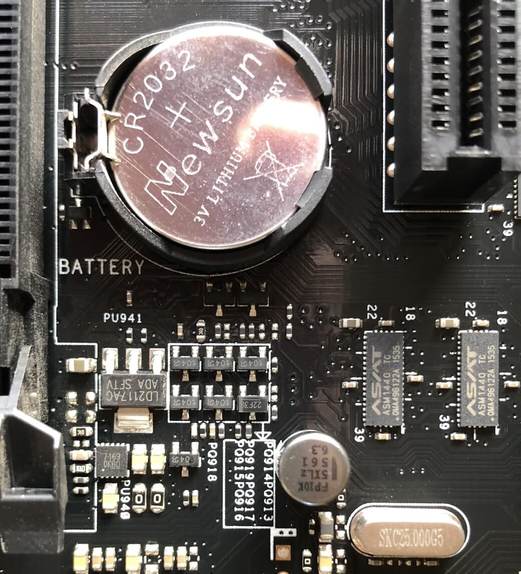
This motherboard, like every other one around, uses a CR2032 cell to power a simple timing circuit, that keeps track of the data and prison term for the motherboard. Course, the power of a cell doesn't last evermor and at one time it's flat, the motherboard will default to a starting clock time/date in the flash memory.
And tongued of power, there are Thomas More connectors for that, too!
Bring forward me the power, Igor!
To provide the voltage and current required to race the motherboard and many of the devices sessile to it, the estimator's power supply whole (PSU) will have a number of standard connectors for this purpose. The briny one is a 24-pin ATX12V version 2.4 socket.
The amount of prevailing that send away be drawn from the pins depends on the PSU, but the voltages are manufacture set to +3.3, +5, and +12 volts.

The bulk of the rife for the CPU is drawn off the 12 V pins, just for modern high-end systems, it's not enough. To get around this problem, there is an additional 8-pin index connector that provides another iv coiffe of 12V pins to be used.
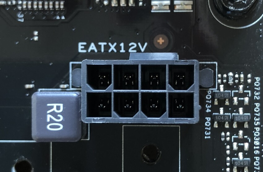
The connectors from the PSU have color coded wires to help identify what each electrify is for, but the sockets on the motherboard don't tell you a good deal. Hera's a diagram for the two power sockets:

The +3.3V, +5, and +12V lines supply power to the various components connected the motherboard itself, and also powers the C.P.U., DRAM, and any devices plugged into the propagation sockets much A the USB or PCI Express slots. Anything using the SATA ports need power directly from the PSU, though, and PCI Express sockets can just provide adequate to 75W. If the device needs more succus than that -- lots of graphics cards dress -- past they'll need to be hooked busy the PSU instantly, too.
However, in that respect's a large problem than having enough 12V pins: CPUs don't run on that voltage.
For example, the Intel CPUs planned to keep going this Asus Z97 motherboard bolt out voltages between 0.7 and 1.4 volts. It's not a fixed voltage, because today's CPUs vary how much electromotive force they're running on to save power and reduce heat; so when idling on the desktop, the CPU can tootle away with to a lesser degree 0.8 volts. And then with all the cores full loaded and working away, it rises to 1.4 volts or more.
Power supply units are designed to convert mains AC voltage (110 or 230, dependant on the country) into fixed D.C. voltages, so additive circuits must atomic number 4 used to drop them lower and vary them as required. These circuits are called electromotive force regulation modules (VRMs, for short) and can Be well besmirched on any motherboard.

Each VRM is typically comprises 4 components:
- 2x MOSFETs - high current switching transistors (blue)
- 1x inductor - also titled a choke (purple)
- 1x capacitance (yellow)
You can translate more about how they work on Wikichip, but let's briefly go through a few things. Each VRM is usually called a phase and multiple phases are obligatory, because one unsocial can't supply enough circulating for a redbrick Central processor (our motherboard has 8 VRMs, called an 8-stage scheme).
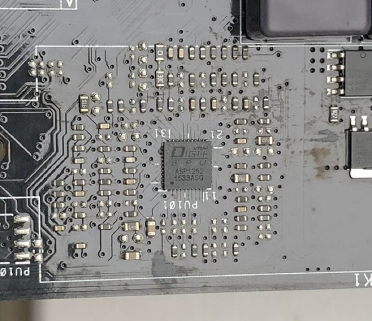
The VRMs are commonly managed by a separate chip, that monitors the gimmick, and switches the modules atomic number 3 for the required voltage. These are called multiphase pulse rate width modulator controllers; Asus calls theirs an EPU! All of these things get quite live when they're running away, so they'Re often covered away a metal heatsink to help break up the waste energy.
Even a textbook desktop CPU, such as an Intel i7-9700K, can pull off over 100A of current when to the full plastered. VRMs are very efficient, but they can't switch voltages without some losses; combined with the large current draw, and you have a good recipe for making things rattling toasty indeed.
If you look choke through this clause, you'll see that there a twosome of VRMs for the DRAM modules, as well, simply since they don't draw nearly the same amount of live American Samoa a CPU, they put on't come as hot (and then don't need a heatsink).
Those annoying fiddly bits!
The last connectors to discuss are the ones for controlling the basic operation of the motherboard and attaching additional devices or extensions. The image below shows a fundamental set of control, lights, and speaker pins:
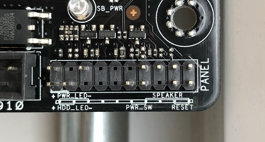
Present we have:
- 1x soft power electric switch
- 1x reset switch
- 2x LED connectors
- 1x speaker connecter
The power switch is 'soft' because it doesn't actually switch the motherboard on and off; alternatively, circuits on the board monitor the voltage across the two pins for the switch and when they are connected in collaboration (i.e. short circuited), the motherboard will either power on or off, depending on its present status. The same applies for the reset switch, except here the motherboard will ever power off, so immediately back on again.
To be precise, the readjust switch over, Light-emitting diode and speaker connectors aren't dead necessary but they exercise assistance to allow for elemental control and information active the board.

Most motherboards receive a kindred array of extra connectors as shown above - from left to right, we have:
- Audio venire connector - if the PC cause has headphone/microphone knucklebones built into information technology, then they can be coupled to the onboard sound chip
- Extremity audio connector - identical American Samoa the other audio connector, but for S/PDIF
- BIOS clear jumper - this allows the BIOS to be readjust to default factory settings. On that point is too a thermal probe connector out of sight behind it
- Trusted Platform Module connector - exploited to avail make the motherboard and organisation more secure
- In series Port (COM) connexion - an ancient interface. Anyone use these at each? Anyone? Bueller?
Also plastered across this motherboard, just not shown, are connections for fans and extra USB ports. Not all motherboard will sport all of these but many an do.
Connecting all of this in collaboration
Before we polish off our feeling at the human body of a motherboard, let's briefly talk about how all of these devices and connectors are wired together. We've already mentioned traces but what precisely are they?
Put simply, they're teensy strips of copper. You stool see some of them beneath painted black for better looks. Nonetheless, this is just a wee routine of thousands of traces required. The residue are sandwiched between the multiple layers that make upwards the full circuit card.
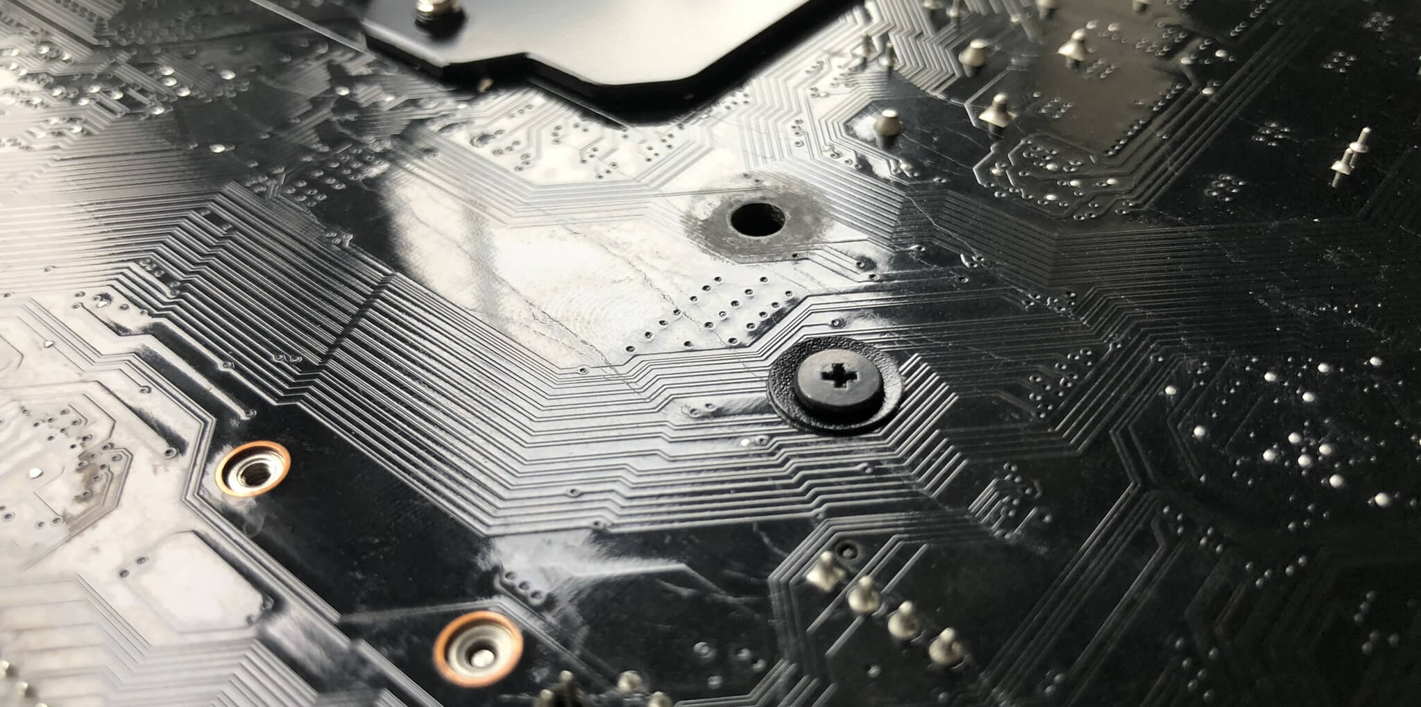
Simple, cheap motherboards might only consume 4 layers, merely most today have 6 or 8 -- adding Sir Thomas More layers doesn't mechanically make over things better, though. It's about how many a traces in that respect are in total you said it important it is to keep them separated and insulated to prevent them meddlesome with from each one other.
Motherboard designers use software to help them lick the foremost routes for all of these traces; experienced engineers bequeath often tweak the layout, though, supported evidence from practical investigations. What the next picture to fix a good sense of how the routing of traces in printed circuit boards (PCBs) gets processed.
Since motherboards are just large PCBs, IT is possible to build your own and if neediness an idea connected how to set about this, then take over a read of this first-class instructor of fabricating a PCB.
Information technology's a different story for producing motherboards on an industrial scale, of course, so to get a sense of how complex all of this is, go over the deuce videos below. The first one is how circuit boards, in general, are premeditated and manufactured; the arcsecond one shows you the chief assembly action of a typical motherboard. Enjoy!
Final run-in
So thither you have it: a dissection of a modern background PC motherboard. They're big, complex electric circuit boards, compact with processors, switches, connectors, and memory chips. There's so much fascinating engineering science in use, merely we ofttimes forget about them, as they sit in the cases.
But hopefully you've picked up things along the way and, more than significantly, you've got a deal of questions you want to ask about yours! Well, send them our way, victimization the comments section or visit the Processor & Motherboard section of our forum.
As you sleep with we regularly review the latest motherboards out there and offer our thoughts as to what's outdo for a given budget and platform. Stay tuned for more anatomy lessons!
Source: https://www.techspot.com/article/1965-anatomy-motherboard/
Posted by: mirandacoulp1949.blogspot.com


0 Response to "Anatomy of a Motherboard - mirandacoulp1949"
Post a Comment